Calibration
Once a sequence is loaded, images can be calibrated, registered and stacked. The calibration is an optional, yet important, step and involves bias, dark and flat frames. Calibrating a sequence in Siril can only be done with master bias, dark and flat frame, which have to be created from their sequences first.
Master files
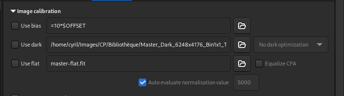
Masters settings of the Calibration Tab
Bias
Citing from A Glossary of CCD terminology, to explain what a bias image is:
The bias level of a CCD frame is an artificially induced electronic offset which ensures that the Analogue-to-Digital Converter (ADC) always receives a positive signal. All CCD data has such an offset which must be removed if the data values are to be truly representative of the counts recorded per pixel.
To use master-bias in Siril, click on the button to the right of the text entry and browse your files to select the right master. You can even use master-bias from a library as defined in the preferences.
Tip
The bias frame must be taken with the shutter closed and the shortest possible exposure time. Basically it corresponds to an exposure of 1/4000s with modern DSLRs.
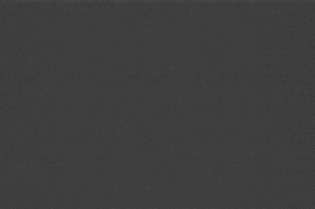
Example of a bias frame that was shot with a Canon EOS 1100D. Do not rely on the slightly visible bias signal, the image is auto-stretched and the differences in signal amplitudes are very exaggerated.
Synthetic bias
Since the offset signal is very uniform on modern sensors, we recommend processing it as a constant level image. This has the advantage of saving disk space and minimizing noise in the final image. For this purpose, Siril has a feature that makes it very easy to do.
During preprocessing of your flats, instead of specifying a masterbias, you can directly type expressions in the folder selector such as:
=2048
or, if the FITS header contains the OFFSET keyword,
=64*$OFFSET
The = and $ tokens are mandatory. The level must be given in ADU (not
float, even if you are working in 32-bit).
Translated into the scripting language, this is written:
preprocess flat -bias="=64*$OFFSET"
The value 2048 is here an example taken for cameras whose master-bias would have a median value of 2048. Generally, for DSLRs, the value is proportional to a root of 2. In our example, \(2048 = 2^{11}\).
Fore more details, please refer to the tutorial on the Synthetic biases.
Dark
Dark frames contain the thermal noise associated with the sensor, the noise being proportional to temperature and exposure time. Hence, they should be made at approximately the same temperature as the light frames, this is the reason why we make dark frames at the end, or in the middle of the imaging session.
To use master-dark in Siril, click on the button to the right of the text entry and browse your files to select the right master. You can even use master-dark from a library as defined in the preferences.
Tip
Dark frames are made at the same exposure time and ISO/Gain than the subject light frames but with the shutter closed.

Example of a dark frame taken with a Canon EOS 1100D with an 300s exposure and at ISO 800.
An animation showing the removal of the thermal signal thanks to the dark subtraction.
Dark optimization
The dark optimization option is useful when dark images have not been taken under optimal conditions. Siril offers two methods with different approaches, accessible via a drop-down list.
With the option Auto-evaluation, dark subtraction can be optimized so that the noise of the resulting picture (light frame minus dark frame) is minimized by applying a coefficient to the dark frame.
The second option, Use exposure, is based on the exposure times of the images if they have been registered in the FITS keywords.
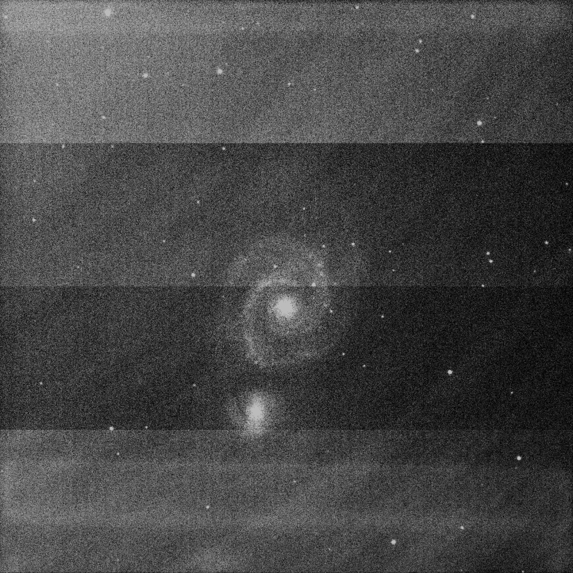
Here's an example of a situation where the use of this option is necessary. The images were taken with a FLI ProLine 4240 camera. The master-dark used comes from a library and was made with an exposure of 600s. Each subs, on the other hand, have exposures of 60s. The master-dark has a very distinctive and rather unsightly signal signature: the presence of 4 preamplifiers in the camera is the cause of such a signal. This defect is obviously also present in the galaxy image, and calibration of the dark must be meticulously carried out to obtain an image free of all defects.
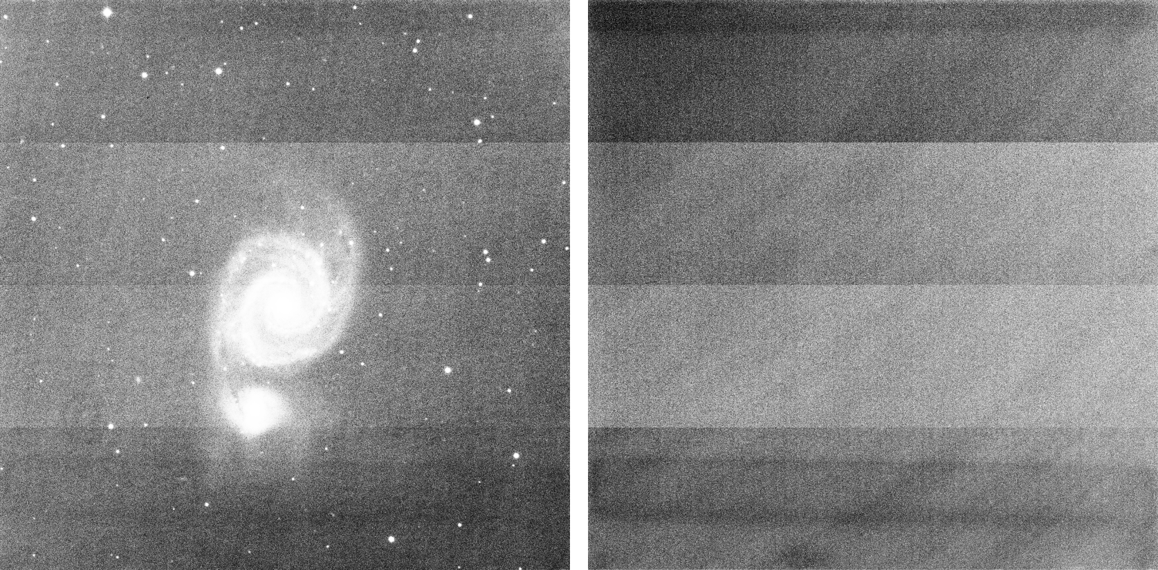
This is a light frame and the master-dark of the FLI ProLine 4240 camera. You can see 4 very distinctive bands caused by the preamplifiers visible on both, lights and master-dark. The images are displayed in histogram equalization mode, to highlight any defects.
However, in this case, if we use the usual workflow, the calibration result will be very poor. This is because the dark master was not taken under the same exposure conditions.
Using the classic workflow, calibration is poor and defects are not corrected. The image is displayed in histogram equalization mode, to highlight any defects.
The solution is therefore to subtract the bias to the dark, then integrate the bias subtraction with those of the images, and check the dark optimization box. Siril will automatically calculate a coefficient to be applied to the dark. Here, it calculates 0.110, which is very coherent, as it corresponds to the 10-fold difference between darks and images (\(60 / 600 = 0.1\)).
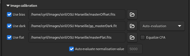
The calibration tab as it should be completed in such a case. Master-flat and master darks have been calibrated by biases.
10:34:58: Preprocessing...
10:34:58: Normalisation value auto evaluated: 0.313
10:34:58: 13230 corrected pixels (0 + 13230)
10:34:59: Dark optimization of image 0: k0=0.110
10:34:59: Saving FITS: file pp_M51SDSSr_00002.fit, 1 layer(s), 2048x2048 pixels, 32 bits
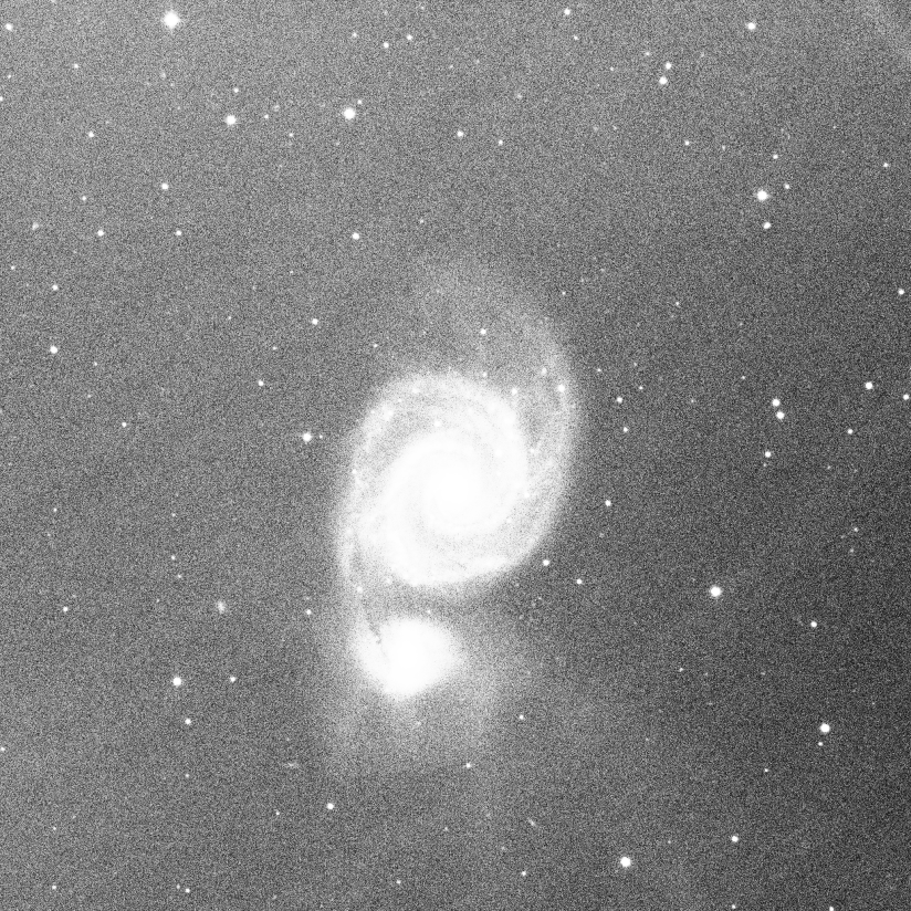
Thanks to dark optimization, calibration is correct. The only residue visible is CCD fringing in the near IR range, which cannot be removed by calibration. The image is displayed in histogram equalization mode, to highlight any defects.
Flat
Telescopes generally do not illuminate the detector evenly. In addition, dust on the optical surfaces and the sensor causes darker patterns in the resulting image, and the sensor itself reacts differently to the number of photons striking different photosites. To correct for these effects, each bright image must be divided by the master flat, which should be the median of the single exposures of a homogeneous and unsaturated area.
To use master-flat in Siril, click on the button to the right of the text entry and browse your files to select the right master. You can even use master-flat from a library as defined in the preferences.
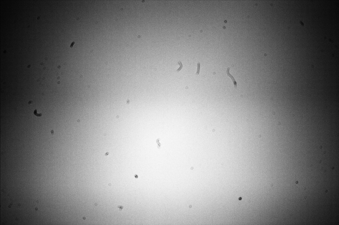
Example of a flat frame that was shot with a Canon EOS 1100D. The dust present on the optical path, and especially on the sensor, are clearly visible. The vignetting (darkening of the corners of the image) is also very visible. The defects are exaggerated by the viewing mode. Also, the grey_flat command was used on this image to get rid of the Bayer pattern.
CFA equalization
The Equalize CFA option equalizes the mean intensity of RGB layers in a CFA flat image. This is equivalent to apply the grey_flat command.
Siril command line
grey_flat
Auto evaluate normalisation value
If the Auto evaluate normalisation value option is checked, Siril will auto-evaluate the normalisation value. This value is the mean of the master-flat calibrated with the master-bias. Otherwise, the value indicated in the text box will be taken into account.
Calibration of light images
The calibration of the light images consists in applying the master bias, dark and flat to the astronomical images in order to remove the unwanted signal.
Warning
In no case does the calibration reduce the noise of the images. On the contrary, it increases it. This is why it is important to take as many calibration images as possible, such as darks, in order to minimize the amount of noise in the images.
Fix X-Trans AF artifact
This Fix X-Trans AF artifact option helps to fix the Fujifilm X-Trans Auto Focus pixels. Indeed, because of the phase detection auto focus system, the photosites used for auto focus get a little less light than the surrounding photosites. The camera compensates for this and increases the values from these specific photosites giving a visible square in the middle of the dark/bias frames. This option has no effect on Bayer pattern. The option is only enabled if a master-bias or master-dark is loaded and used.
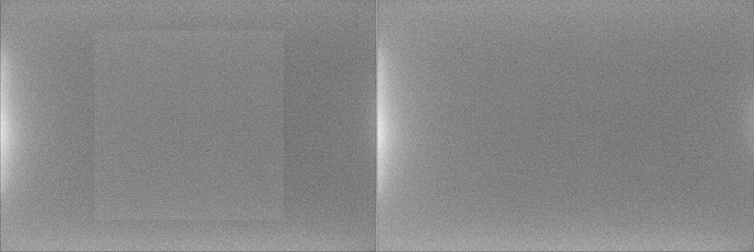
X-Trans artifact fixed by the algorithm of Siril
Cosmetic Correction
Cosmetic correction is the technique used to correct defective pixels in images. Indeed, any camera sensor has photosites that do not react correctly to photon reception. This is visible in the image with pixels with values very different from those of their nearest neighbors. These pixels are called hot pixels, if the value is much higher, or cold pixels when it is much lower. Siril offers two algorithms to correct these defective pixels if the option Enable Cosmectic Correction is checked.
Using Master-Dark
This method requires the presence of a master-dark. Siril will search for pixels whose deviation from the median exceeds x times the standard deviation \(\sigma\). This value is adjustable for both hot and cold pixels.
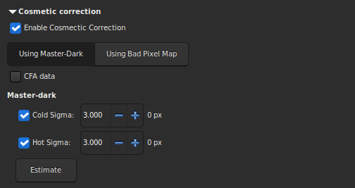
It is possible to estimate the number of pixels that will be corrected in the calibrated image by pressing the Estimate button. If the corrected pixel value is displayed in red, it means that this number exceeds 1% of the total number of pixels in the image. In this case you should increase the value of the coefficient, or uncheck the corresponding correction. If the images are from a color sensor then it is necessary to check the CFA option.
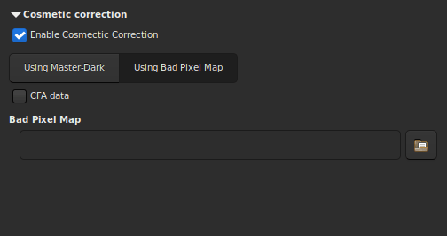
Using Bad Pixel Map
The other method uses a file that contains the coordinates of the defective pixels. This file is a simple text file and can initially be created with the command find_hot. The last line has been added by hand and corrects a damaged column located at position \(x = 1527\).
P 325 2855 H
P 825 2855 C
P 838 2855 H
P 2110 2855 H
P 2702 2855 H
P 424 2854 H
C 1527 0 H
Siril command line
find_hot filename cold_sigma hot_sigma
P x y type will fix the pixel at coordinates (x, y) type is an optional character (C or H) specifying to Siril if the current pixel is cold or hot. This line is created by the command FIND_HOT but you also can add some lines manually:C x 0 type will fix the bad column at coordinates x.L y 0 type will fix the bad line at coordinates y.This file, which can be edited by hand, is to be loaded as a Bad Pixel Map.
Finally, if the images are from a color sensor then it is necessary to check the CFA option.
Output sequence
This section groups the options that can be applied to the output.
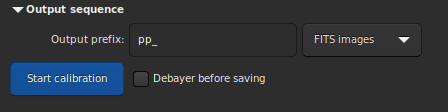
The Output Prefix entry box adds a prefix to the output images, to easily identify them. By default, the prefix is
pp_, which means pre-processed.The drop-down list defines the type of destination sequence.
FITS images: one FITS file per image.
SER sequence: one SER file for the whole sequence (limited to 16 bits per channel).
Sequence FITS: one FITS file for the entire sequence.
Last option, Debayer before saving. Check this option if you want to apply a demosaicing algorithm to your frames right after they were calibrated. By doing this, you skip one manual step which can take some time.
Command lines
Siril command line
calibrate sequencename [-bias=filename] [-dark=filename] [-flat=filename] [-cc=dark [siglo sighi] || -cc=bpm bpmfile] [-cfa] [-debayer] [-fix_xtrans] [-equalize_cfa] [-opt[=exp]] [-all] [-prefix=] [-fitseq]
Siril command line
calibrate_single imagename [-bias=filename] [-dark=filename] [-flat=filename] [-cc=dark [siglo sighi] || -cc=bpm bpmfile] [-cfa] [-debayer] [-fix_xtrans] [-equalize_cfa] [-opt[=exp]] [-prefix=]
Understanding how the flats correct the lights
The point of this section is to give a bit more insight in how the different levels play a role in the correction of the lights by the flats.
We will disregard here any considerations about noise (again, noise does not vanish with masters subtraction or division, it decreases by averaging over many realizations of the same random process). We also disregard particular spatial patterns such as ampglow or dust.
If we try to quantify the intensity of background pixels in the different frames we have, we can write the following expressions:
with, \(L\) for Lights, \(D\) for Darks, \(F\) for Flats and \(O\) for Bias.
For the lights \(L\), the first part is a spatial illumination component, i.e., \(a - b(x-\frac{W}{2})^2\). We have chosen here a quadratic variation with a maximum value \(a\) in the middle of the frame of width \(W\), even about the center of the sensor. This is not the exact spatial shape of vignetting but it is a good enough approximation to understand how it works. In addition to this spatial illumination term, there is a term varying with exposure time which is usually named dark current (\(d_\text{rate} \times t_\text{lights}\)) but which does not depend on the position of the pixel on the sensor. And finally there is a pedestal, i.e. the offset. This offset is present in any frame which is shot, so that we find it in all the expressions.
The darks \(D\) not being illuminated, they only bear the dark current term, with same intensity as lights as they are shot for the same amount of time, and the offset term.
The flats \(F\) also have a spatial term, proportional to the term found in the lights. The factor \(K\), larger than 1, simply shows that their intensity is larger. To write this, we only need to assume that the pixels respond linearly to the number of photons they gather, which is sensible. We could also have written a dark current term, proportional to the exposure time of flats. But unless this time is significant, we can assume it is negligible. If it is not the case, then it means you need to shoot dark flats, or at least to assess their level.
And finally the offsets \(O\) only measure the offset level.
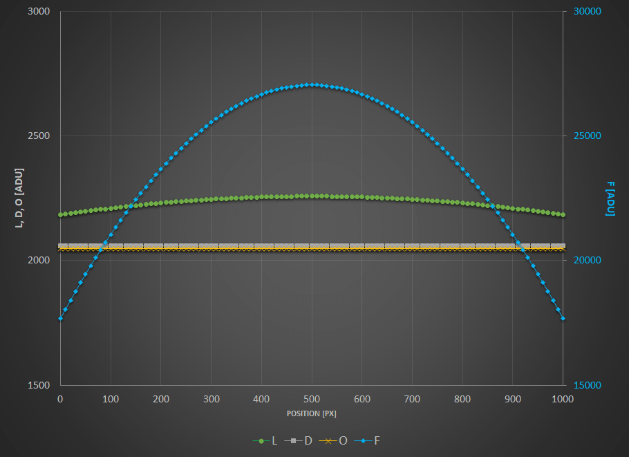
To visualize these levels, we have plotted here-below these expressions as curves wrt. position on a frame and we encourage you to do the same and to play around with the inputs.
\(a = 200 \text{[ADU]}\)
\(b = 0.0003 \text{[ADU/px}^2\text{]}\)
\(d_\text{rate} = 1 \text{[ADU/s]}\)
\(t_{\text{lights}} = 10 \text{[s]}\)
\(o = 2048 \text{[ADU]}\)
\(W = 1000 \text{[px]}\)
\(L\), \(D\) and \(O\) values in ADU are given on the left scale while \(F\) are on the scale reported to the right.
Now what does calibrating your lights mean? When you calibrate your lights, you perform the following operation:
The term \(F-O\) is a flat from which you have subtracted the offset level (whether it is a masterbias or simply a level). This is the operation performed prior to stacking your masterflat. And the term \(L-D\) represents a light from which you have subtracted the dark current level and the offset, i.e. a masterdark. If you replace with the expressions shown above, you end up with the following:
No spatial variation term is left, you have flat-fielded your lights! Getting a sensible value in ADU (and not \(1/K\)) is what Siril does when you check Auto evaluate normalisation value in the Calibration tab.
And you can try with any other combination, no other will get rid of spatial variations.
Just to illustrate this, We have plotted below the result of different combinations. To put everything on the same scale, all the results are normalized to have the same intensity of 1 in the middle of the frame. The following tests are shown:
\(L-D\) : you have just shot darks.
\(L/F\) : you have just shot flats.
\(L/(F-O)\) : you have shot flats and corrected them by an offset (either a master or a synthetic one).
\((L-O)/(F-O)\) : you have just flats corrected by offset. But you have subtracted the offset from your lights as well.
\((L-D)/F\) : you have shot flats and darks but no offsets.
\((L-D)/(F-O)\) : you have done everything by the book.
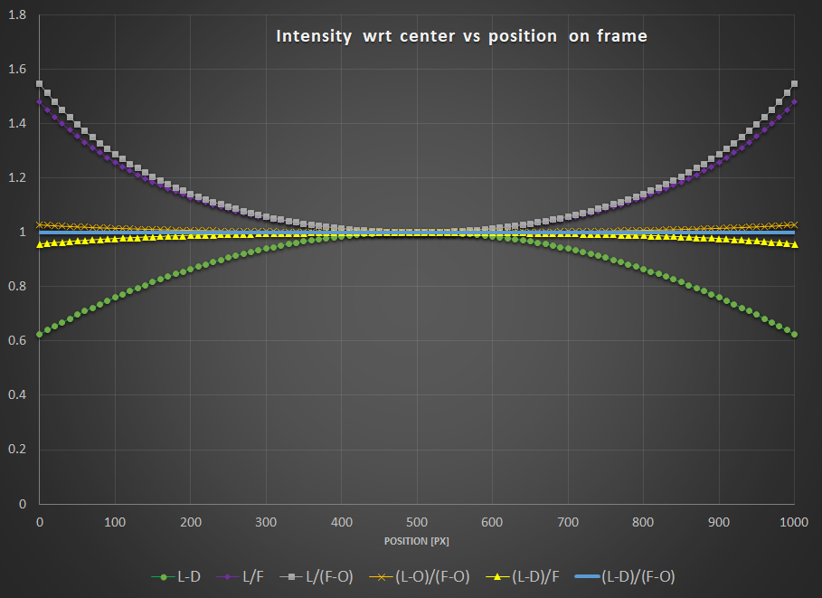
Interestingly, you can notice that:
\(L-D\) shows obviously no correction for vignetting.
Both \(L/F\) and \(L/(F-O)\) show overcorrection or inverse vignetting.
Getting very close to the optimal result, \((L-D)/F\) and \((L-O)/(F-O)\) shows a field almost flat. This, of course, will depend how much your sensor has dark current and how much vignetting your optical train shows.
The reference calibration gives a flat field.
The conclusions that you can draw from the above are:
You are better off correcting your lights with offset (masterbias or simply a level) if you have not shot darks.
Even better, if you don't have time to shoot a series of darks, it is probably worth shooting at least one dark, measure its median, and subtract this (synthetic) dark from your lights. It will of course not correct for ampglow or enable hot pixel correction, but your lights will at least be flat!
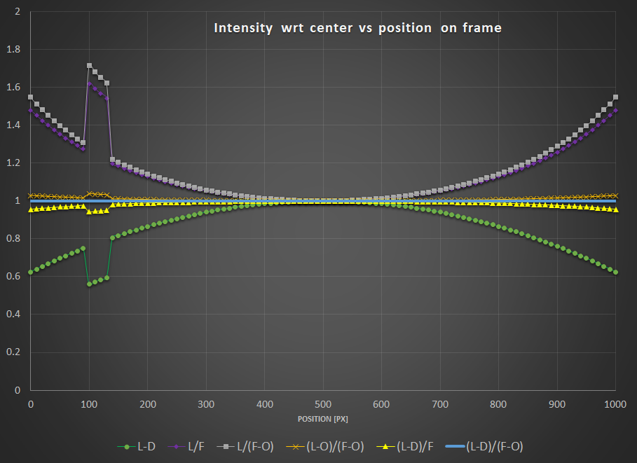
Now what about dust...?
In order for your flats to also correct for these nasty spots, the sad news is you also need to get all the calibration frames in the equation. We have added a small local ADU deficit in the lights and flats to illustrate this effect.
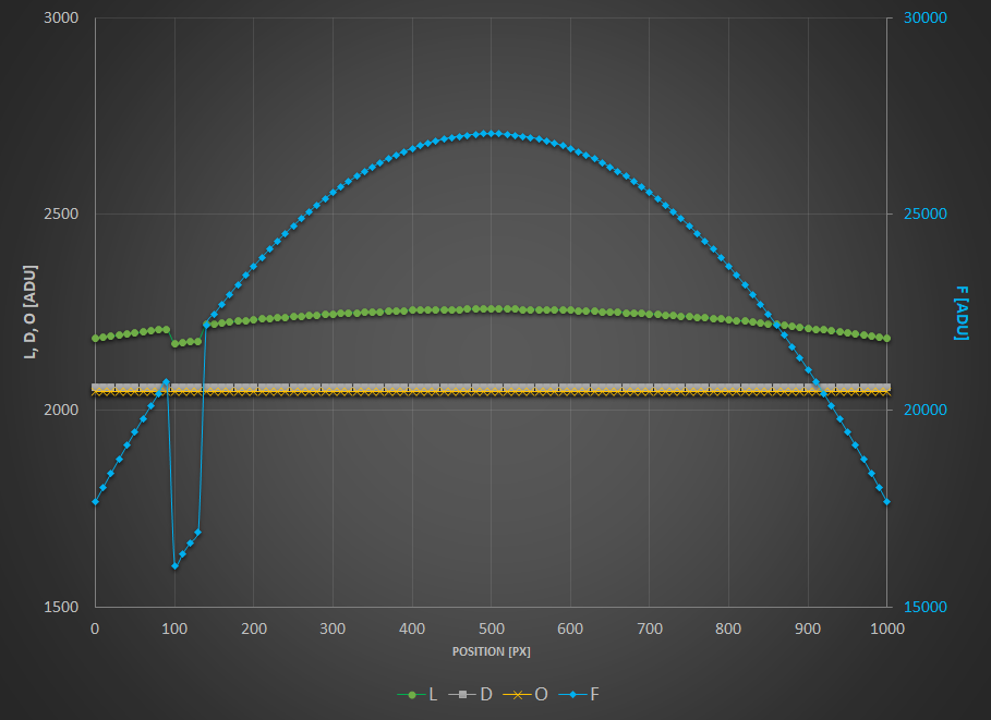
As you can see, only the combination \((L-D)/(F-O)\) can get rid of it.
To further illustrate the equations and curves above, nothing is better than a real-life example. All pictures below are shown courtesy of G. Attard.
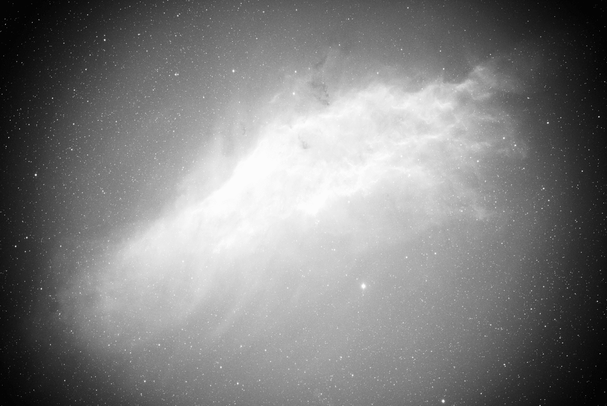
\(L-D\)

\(L/F\)
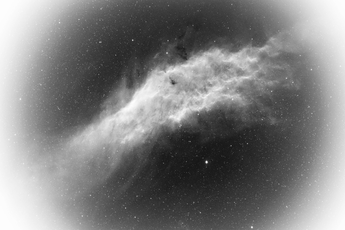
\(L/(F-O)\)

\((L-O)/(F-O)\)
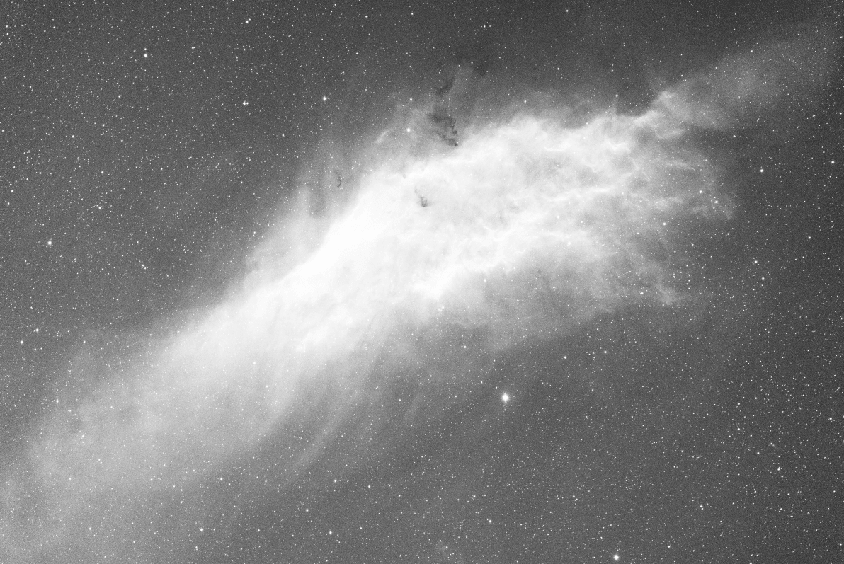
\((L-D)/(F-O)\)
Troubleshooting calibration
Calibration is a very simple step arithmetically, and cannot fail if the input data conforms to what is expected for astronomical images.
However, users are regularly confronted with situations where the calibrated images are not correct. In this section, we'll give you an overview of the problems encountered and how to avoid them.
First of all, the statistic tool is an invaluable aid to understanding problems, and is used in the majority of cases to fix issues.
When analyzing the statistics of a master-dark, it must first be black. This is because these images are taken with the cap closed, and there's no reason why one of the photosites should be privileged. The image must look as if it had been taken by a monochrome sensor, with the Bayer matrix not visible. Below, here's an example where the master-dark has undergone an unwanted color balance for this type of image. As a result, it is no longer black and the Bayer pattern is visible. Such a dark is unfit for use and must be remade.
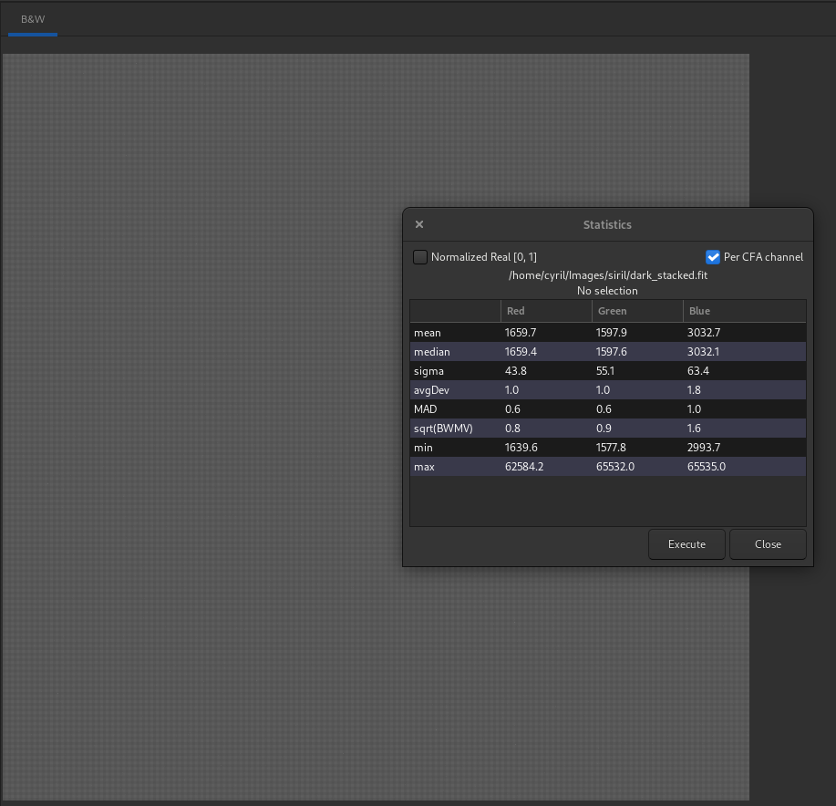
A close look at the statistics shows that the median value of each channel is different, whereas they should be identical (or almost). Also, Bayer's pattern is clearly visible.
During the night session, it's very important to set the OFFSET value to the same value for all images. Particularly it is mandatory to have the same setting for the pairs darks/lights and bias/flats. Failing to meet the first condition may end up in losing significant data (clipping pixels to the left hand side of the histogram). Failing to meet both conditions will most probably prevent your images to be correctly flat-fielded (see section above).
Check darks and lights levels: the median value of lights images must be sufficiently higher than that of darks to avoid generating images full of pixels with negative values.
If you have used the same settings for darks and biases, their median values should be very close to each other (at least with a cooled camera). Otherwise, it may mean you have you have a light leakage that has affected your darks (biases are less sensitive as they are exposed for a much shorter time). So always inspect your master-dark to see whether there's a gradient or a brighter patch in the center. This is not to be confused with ampglow which is normal for certain cameras.
We strongly recommend that you shoot your images in the same way: same software / same computer or astrobox /same image format. In fact, each program may use its own writing conventions, and images may no longer be compatible with each other. We often hear of users making all their images with an astrobox, and making the flats the next day directly with their DSLR. In this case, the images are often of different sizes, making calibration impossible.
An error often encountered when running a script is the presence of JPG images in one of the input folders (darks/biases/flats/lights), most times snapshots saved by the acquisition software for faster browsing. The consequence of this kind of error is that calibration fails and stops, complaining that the images are not of the same size. In fact, since JPG images are already demosaiced, they have three channels, while RAW images have only one. Remove all JPG images from the input folders to fix this issue.
Check that the flat is not overexposed. Flat frames are used to correct for pixel-to-pixel sensitivity variations in the sensor. If some pixels are overexposed, their true sensitivity may not be accurately represented, leading to incorrect corrections during the calibration process. An overexposed flat is the guarantee of a failed calibration.
To check for overexposed pixels, you can load a flat subframe and use the to show the histogram of the image. The snapshot below shows that one of the peaks is clipped to the right. As a prudent approach, you should always check that the right tail of the peak furthest to the right is not above 80%, to avoid going in a zone where your sensor may become non-linear.
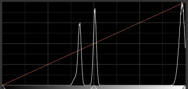
White-clipping of a flat. When this happens, it means you should lower the gain or the exposure time.